The image filters tool allows you to refine the display of images in each channel by adding different color options, image processing filters, and by controlling the composition of the Overlay channel.
To open the image filters tool, click the Image Filters tool button, shown with a red highlight in Figure 1, in the images browser display controls panel. The image filters tool displays as a separate window.

Figure 1 Image filter tool highlighted
You can also open the image filters tool by double-clicking an image on the image wall or by navigating to the images browser menu bar and by clicking Tools > Open Image Filter Tool.

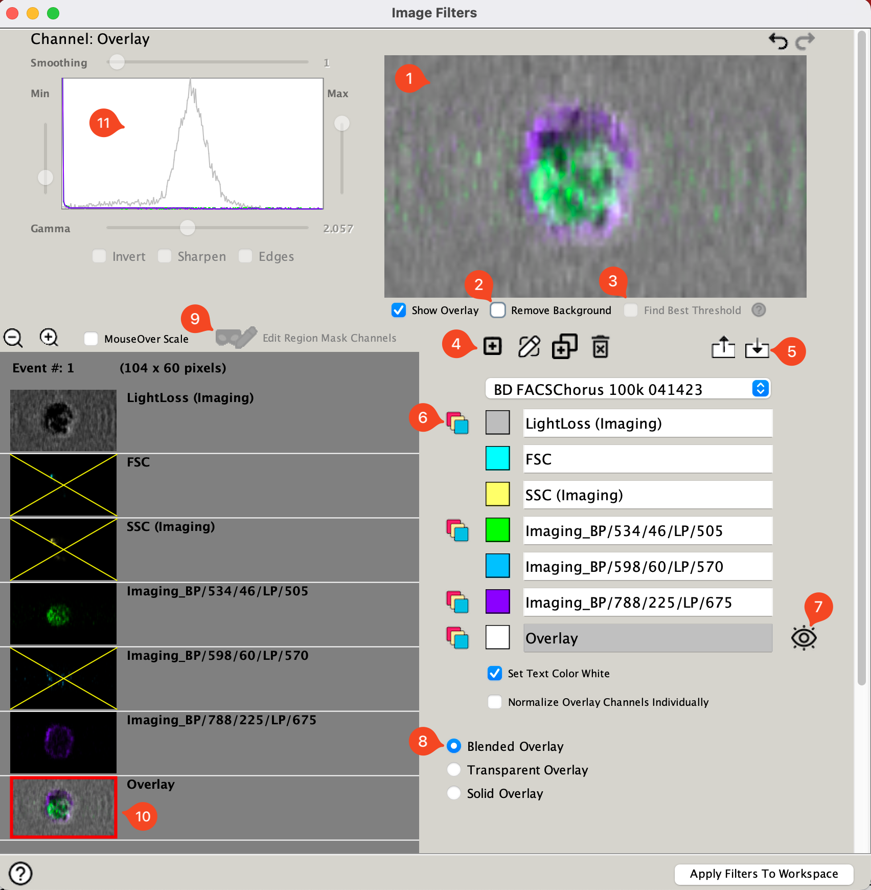
Figure 2 Many controls are available within the Image Filter Tool
| No. | Tool Description |
|---|---|
| 1 | Image preview. Displays either the selected channel or all active channels if Show Overlay is selected |
| 2 | Remove Background. Using the Region Mask Channel(s) (see No. 9), contiguous edges will be identified and any signal outside that region will be removed as background. |
| 3 | Find Best Threshold. If Remove Background is selected checking this box will use an algorithm to identify the optimal boundary. |
| 4 | Create, rename, duplicate, or delete filter set. Organizational tools for filter sets |
| 5 | Save or load filter sets. Particularly well crafted filter sets can be saved as an external file and imported into other workspaces. |
| 6 | Channel controls. Clicking to the left of the color box will make a channel active and turn on the blue/yellow/box icon. Active channels will be used to create the overlay image and can be viewed in the image wall. Clicking on the colored box will change the highlight color of the channel. |
| 7 | Displayed channel indicator. The eye icon next to a channel displays which channel will be displayed in the image wall (if you are in channel view, all active channels will be displayed). Clicking to the right of any channel will move the eye to that channel. Only one channel can be the displayed channel at a time. |
| 8 | Overlay options. Select Blended, Transparent, or Solid to control how the colors are mixed from multiple channels. |
| 9 | Edit Region Mask Channels - If Remove Background is checked on clicking this button will show a mask icon for each channel used to determine the image mask, meaning the edge of the identified cell(s) that will be kept after background removal. Control-clicking on any channel will toggle it on/off. If edit region is selected, the Show Overlay button becomes the Show Region Mask button, which allows you to display the area identified as 'cell' vs. noise that will be removed. |
| 10 | Channel controls. The red box indicates which channel is being edited currently. Double clicking on a channel toggles it on/off. |
| 11 | Channel manual editing tools. These tools can be used to adjust smoothing, and display thresholds for the selected channel. |
When the first BD_CellView_Lens node is created, the plugin will import the filter set used in Chorus during acquisition from the fcs file as the default filter set. Figure3 displays the Filter set selection tool. Other default filters are available such as AutoColor and AutoColor Smoothed. Using the Filter tool you can also import a filter previously aved.

Figure 3 Filter set selector
Overlays
In addition to the individual images for each channel, the BD CellView™ Lens plugin creates an additional Overlay channel that combines the enabled channel images to make a single channel image. The images are overlaid in the order shown in the channel list, which can be rearranged using the up and down arrow buttons located next to the channel names, which appears when Transparent or Solid overlays are selected.
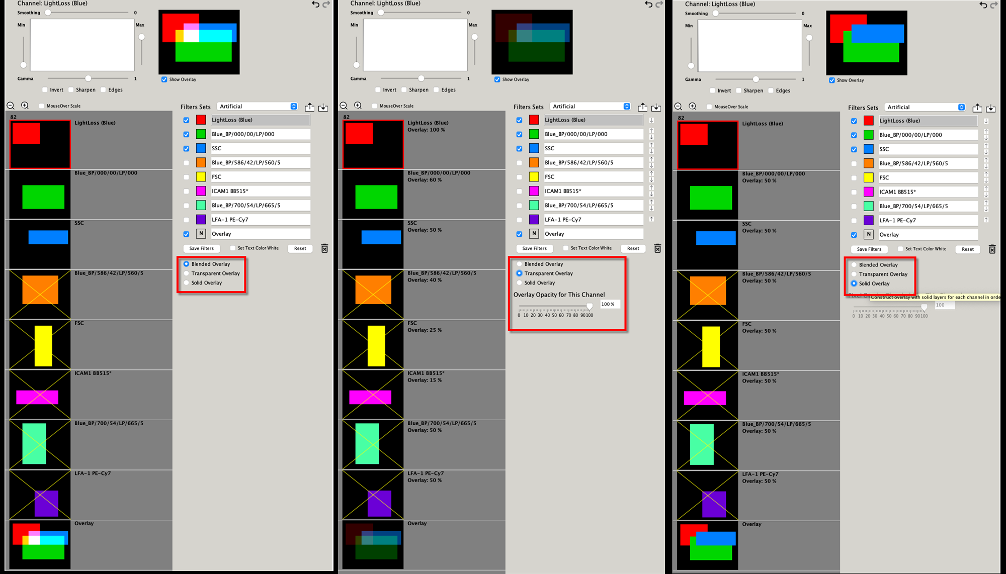
In a blended overlay, the color of an individual pixel in an image is determined by adding the color of that pixel from each enabled channel. For example, if the color for the pixel in channel 1 is red and the color in channel 2 is green, the resulting pixel is colored yellow. Note: The order of the channels does not affect the final pixel color. A blended overlay implements a technique called ‘additive blending’, where each pixel in the overlay is constructed by adding the weighted pixel RBG values for each channel color.
A transparent overlay is constructed by stacking the channel images on top of each other, where the
amount shown for a specific channel is determined by its opacity setting, between 0 and 100%. If using transparent layers, you can set the opacity for each channel using the slider bar. You should adjust the opacity for each channel as it is overlaid, so that each channel shows through in the Overlay channel. For each channel as the opacity number is decreased or increased, the opacity increases or decreases, and less and more of the other channels will be seen through the current channel in the overlay, respectively. To help ensure that each layer is displayed and not blocked by a following layer, it is recommended that the first layer is set to 100%, and subsequent layers set 70% or lower, and a layer’s opacity is not greater than the one before (for example: 100%, 70%, 50%, 30%, etc.)
A solid overlay uses full color for each channel over the set threshold, and plots the colors in the order of the channels. Use the slider bar to set the Pixel Overlay Threshold to determine whether a pixel from the channel image is included in the overlay image or not. The intensity of each pixel in the image is normalized to a percentage of the intensity range, and is compared to the threshold value. For example, you can specify that the top %50 brightest pixels for Channel X are used when constructing the Overlay.
Normalization is required to scale the range of color per channel. By default the normalization is global across all channels. Just above the Overlay selections there is a checkbox that allows you to normalize each channel individually so that you might emphasize colors that are not brightly expressed, but an increase in signal is significant.
To help visualize the different types of overlays and how they are composed, the Image Filters Tool can be opened to display a preview of artificial channel images composed of overlapping rectangles for each channel. To open the image filters preview tool, press the [Shift] key and double-click on an image in the image wall. Using the image filters preview tool, you can select or clear channels and set their colors to illustrate how pixel colors are blended, how transparent layers are overlaid, or how solid layers are composed.
The following images are examples of the image filters preview tool with a single channel with the same color selections and with differing overlay variations:

Region masks
Region masks are used primarily to help identify background and remove it. Edges are detected using any parameter or combination of parameters except for light loss. The edge detection tool identifies a continuous perimeter of pixels with color vs. uncolored. Because the region is contiguous two cells touching will be identified as one region. However, more than one region can be identified per event. Multiple regions will be identified via differing color.
Regions are created by checking the Remove Background box, item No. 2 in Figure 1. To remove the background the cell edges must be identified and regions are created. The Find Best Threshold checkbox will automatically detect the regions on a per cell basis. Leaving that off allows the user to use the Edit Region Mask Channels button, item No. 2 in Figure 1, to select which channels will be used for detecting regions and the channel editing sliders to adjust sensitivity manually.
See Using Regions for more information on the utility of regions in the CellView Lens plugin.
